The 9-Minute Rule for Wedge Barriers
Wiki Article
Wedge Barriers for Beginners
Table of ContentsHow Wedge Barriers can Save You Time, Stress, and Money.9 Simple Techniques For Wedge Barriers
Getting My Wedge Barriers To Work
The remaining force used to the cam to deploy the wedge plate 16 may be provided by an electromechanical actuator 84 or other various other. The spring setting up 54 and the actuator 84(e. Wedge Barriers. g., electromechanical actuator)may run with each other to equate the cam and lift the wedge plate 16.
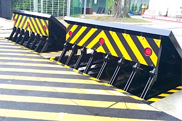
As pointed out over, the spring setting up 54 exerts a continuous pressure on the camera, while the electromechanical actuator might be regulated to apply a variable force on the webcam, therefore making it possible for the lifting and reducing( i. e., deploying and pulling back )of the wedge plate 16. In certain embodiments, the constant force used by the springtime setting up 54 may be adjustable. g., electromechanical actuator) is impaired. As will certainly be appreciated, the spring setting up 54 may be covered and shielded from particles or various other components by a cover plate(e. g., cover plate 68 displayed in FIG. 4) that might be significantly flush with the raised surface 38 of the structure 14. As mentioned over, in the deployed position, the wedge plate 16 offers to obstruct accessibility or traveling beyond the obstacle 10. For instance, the barrier 10(e. g., the wedge plate 16 )may block pedestrians or cars from accessing a property or pathway. As reviewed over, the obstacle 10 is connected to the support 30 protected within the structure 14,
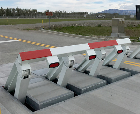
front braces 71. Because of this, the link assemblies 72 may pivot and turn to allow the collapse and expansion of the affiliation settings up 72 during retraction and release of the bather 10. The link assemblies 72 reason motion of the wedge plate 16 to be limited. view website For instance, if a car is taking a trip in the direction of the deployed wedge plate 16(e. For instance, in one scenario, the safety legs 86 might be prolonged throughoutupkeep of the obstacle 10. When the security legs 86 are released, the safety legs 86 sustain the weight of the wedge plate 16 versus the surface 12. As an outcome, the lifting device 50 may be shut down, serviced, eliminated, replaced, and so forth. FIG. 5 is partial viewpoint view of a personification of the surface-mounted wedge-style barrier 10, showing the cam 80 and the web cam surface areas 82 of the training device 50. Particularly, 2 webcam surface areas 82, which are referred to as reduced webcam surface areas 83, are positioned below the camera 80. The reduced webcam surface areas 83 might be taken care of to the surface area 12 (e. For instance, the reduced webcam surface areas 83 and the installing plate 85 may form a solitary item that is protected to the support 30 by bolts or other mechanical directory fasteners. In addition, two camera surface areas 82, which are referred to as top cam surfaces 87, are placed over the camera 80 and paired to (e. In other embodiments, intervening layers or plates might be placed between the surface area 12 and the reduced web cam surface areas 83 and/or the wedge plate 16 and the top web cam surface areas 87 As discussed over, the web cam 80 converts along the cam surface areas 82 when the wedge plate 16 is lifted from the retracted placement to the deployed setting. Additionally, as mentioned over, the spring setting up 54 (see FIG. 3 )may supply a force acting upon the cam 80 in the instructions 102 through spring pole 58, which might minimize the force the electromechanical actuator 84 is required to use to the camera 80 in order to activate and lift the wedge plate 16. 1 )to the deployed placement(see FIG. 4). As revealed, the camera 80 includes track wheels 104(e. g., rollers), which contact and Your Domain Name convert along the camera surfaces 82 during procedure.
Report this wiki page